| vlsitechnology.org /IR drop /example 1 /strap allocation |
Strap Allocation |
IR Drop
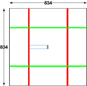
The best layout practice for the standard cells is to lay them in a uniform grid in x and y and then remove the cells where other objects are required. For horizontal power straps, this means that the power straps will replace one or more standard cell rows. The vertical straps' widths are usually linked so that they too will occupy an integer number of row heights.
We consider two factors for the choice of the number of rows.
- If the straps are very wide and spaced far apart, then there will be standard cells which are a long way from the straps. Cells in adjacent rows will have a long metal run separating their power supplies and this can lead to localised voltage differences which could cause timing problems. A finer mesh gives a more even voltage distribution across the core.
- There are bigger spacing rules to wide metal, so even if the strap allocation is doubled, the width isn't. Very wide metal lines also require slotting, and it's better to avoid this complication if possible.
Because of these two factors, as a design choice we choose here to use a narrow power strap allocation of 2 cell rows, 160λ or 8.8µm. On the next pages we will look at the actual strap widths given the following table of metal spacing rules. They have been rounded to lambda values from the original micron design rules. Metal widths are also kept to a 2λ multiple so that the metal edges remain on a 1λ grid.
| width | 4-6 | 8-30 | 32-74 | 76-106 | 108-174 | 176- |
| space | 4 | 5 | 12 | 22 | 37 | 62 |
Next we look at each metal layer in turn and calculate the supply strap width using these rules. These values will be used for the values of kwn, the power strap width coefficient.
